IntroductionFrom the demand side, flexible circuits More in line with the psychological expectations of consumers, willing to pay for the things they like. https://gekunflex.com/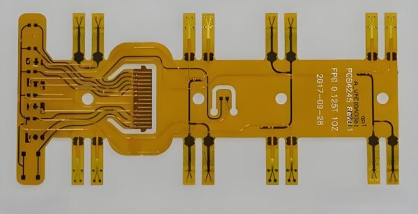
Flexible circuit boards (FPCs) are integral to modern electronics, offering durability, lightweight construction, and adaptability. To ensure that a flexible circuit design meets industry standards and functions effectively, a structured approach is necessary. This guide provides a comprehensive, step-by-step overview of how to create a flexible circuit board design specification .
Table of Contents hide
1 Flexible Circuit Board Design Specification
1.1 1. Understanding Application Requirements
1.2 2. Material Selection
1.3 3. Defining Circuit Configuration
1.4 4. Designing the Layout for Flexibility
1.5 5. Stack-Up Design Considerations
1.6 6. Trace Width and Spacing Guidelines
1.7 7. Via Design and Implementation
1.8 8. Mechanical and Thermal Management
1.9 9. Design for Manufacturability (DFM)
1.10 10. Final Prototyping and Testing
1.11 Conclusion
1. Understanding Application Requirements
The first and most crucial step is identifying the specific requirements of the application. This includes:
Environmental conditions: Consider the temperature, humidity, chemical exposure, and mechanical stress the board will endure.
Electrical performance: Determine the required signal integrity, current handling, and power dissipation.
Mechanical flexibility: Establish whether the board will need to be frequently bent or remain in a static position.
Properly understanding the use case will guide you in choosing materials and design parameters.
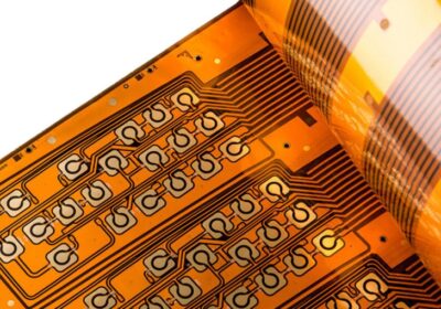
Flexible Circuit Board Design
Flexible Circuit Board Design
2. Material Selection
Choosing the right materials is fundamental to meeting the flexible circuit board design specification. Common materials include:
Base substrate: Polyimide is the most popular due to its high flexibility and temperature resistance. Polyester is also an option for low-cost designs.
Copper foil: Choose the thickness based on the current-carrying requirements and overall flexibility. Thicker copper layers increase durability but reduce flexibility.
Adhesives and coverlays: Use heat-resistant adhesives and flexible coverlay materials to protect the copper circuitry while maintaining board flexibility.
Selecting the appropriate materials ensures that the board can withstand environmental stresses and operational demands.
3. Defining Circuit Configuration
Flexible circuits come in several configurations, depending on the complexity of the design:
Single-sided circuits: Ideal for simple, low-cost designs.
Double-sided circuits: Provide more routing options, allowing for more complex designs without sacrificing flexibility.
Multilayer circuits: These are used for advanced applications that require high-density interconnections and compact form factors.
Select the configuration that best suits your design complexity and space constraints.
4. Designing the Layout for Flexibility
A key design consideration in flexible circuits is how the layout accommodates the board¨s mechanical flexibility. Best practices include:
Avoiding sharp angles: Use rounded corners in traces to prevent stress points during flexing.
Uniform trace width: Keep trace widths uniform to ensure even stress distribution.
Bend radius: Define an adequate bend radius (typically 10 times the thickness of the board) to avoid damage to the circuitry during flexing.
Component placement: Ensure components are positioned away from the bend areas to prevent mechanical damage.
Proper layout optimization will enhance the durability and longevity of your flexible circuit.
Flexible Circuit Board Design
5. Stack-Up Design Considerations
For multi-layer flexible circuits, it¨s essential to plan the stack-up carefully:
Signal integrity: Ensure sufficient separation between signal and ground planes to reduce crosstalk and maintain signal quality.
Thermal management: Balance layers in the stack-up to dissipate heat effectively and avoid overheating during operation.
Bendability: Ensure the outer layers remain flexible, while inner layers may require stiffeners for mechanical support.
A well-balanced stack-up is key to achieving electrical performance and maintaining flexibility.
6. Trace Width and Spacing Guidelines
Trace width and spacing directly influence the electrical performance of the circuit. Key factors to consider include:
Current carrying capacity: Use wider traces for higher currents, but avoid overly wide traces that reduce flexibility.
Impedance control: For high-speed signals, calculate and maintain controlled impedance to prevent signal loss or degradation.
Adequate spacing: Ensure that trace spacing meets the electrical isolation requirements to prevent shorts or arcing.
Following manufacturer guidelines for trace width and spacing will ensure the circuit performs reliably.
7. Via Design and Implementation
Vias play a critical role in connecting different layers of a flexible PCB. The most common types include:
Through-hole vias: Best for simple, cost-effective connections.
Blind/buried vias: Used in complex designs to connect specific layers without penetrating the entire stack.
Microvias: Essential for high-density designs, especially in space-constrained applications.
Selecting the appropriate via type ensures efficient routing while maintaining board flexibility.
8. Mechanical and Thermal Management
Given the operational environment, it is crucial to design for both mechanical and thermal stability:
Reinforce stress areas: Stiffeners can be applied to areas that experience high mechanical stress to prevent circuit breakage.
Thermal reliefs: Design with thermal management in mind, especially for power circuits, to ensure heat is dissipated and doesn¨t compromise the board¨s operation.
Thermal and mechanical considerations enhance both reliability and performance, particularly in demanding applications.
Flexible Circuit Board Design
9. Design for Manufacturability (DFM)
After completing the design, it¨s important to test for manufacturability to ensure the design can be efficiently produced:
Adhere to manufacturing tolerances: Work closely with your manufacturer to ensure the design meets their production capabilities.
Minimize material waste: Optimize the layout to reduce the cost and complexity of production.
Test flexibility and durability: Simulate the bending and environmental conditions the board will face in its final application to confirm robustness.
Addressing DFM early in the design process will reduce production errors and lower costs.
10. Final Prototyping and Testing
Before full-scale production, create a prototype of the flexible circuit:
Test for functionality: Check that all electrical components and signals are working as intended.
Verify mechanical properties: Bend and flex the prototype to ensure it meets flexibility requirements without failure.
Environmental testing: Subject the board to temperature and humidity cycles to confirm it can withstand operating conditions.
Prototyping helps identify any issues in the design and ensures that the final product meets all specifications.
Conclusion
Designing a flexible circuit board requires a meticulous approach that balances electrical performance, mechanical flexibility, and manufacturability. By following the steps outlined in this guide, you¨ll ensure your design meets industry standards and performs optimally in its application. For high-quality production, collaborating with an experienced manufacturer like Gekunflex can further enhance the success of your flexible circuit board project.