Ultrasonic vs. Optical Fingerprint Recognition Two Major Choices for Smartphone Security Technology

  In the digital age, smartphones have become an indispensable part of our lives, and fingerprint recognition technology provides convenience and security for device protection. Today, two main types of fingerprint recognition technologies are commonly used in smartphones: ultrasonic fingerprint recognition and optical fingerprint recognition. Although both serve the same core purpose of enhancing user security and convenience, they differ significantly in working principles, performance, applicability, and security. This article will provide a detailed comparison of these two technologies, helping users understand their advantages and disadvantages and choose the best option for their devices.in fact Laser sensor Our related products were once praised by users, which is the best self-affirmation of the products. https://www.hfyakexi.com/


  Ultrasonic Fingerprint Recognition


  Working Principle


  Ultrasonic fingerprint recognition technology uses high-frequency ultrasonic pulses to detect the fine details of fingerprints. When a user places their finger on the sensor, the sensor emits ultrasonic signals that penetrate the surface of the fingerprint and are reflected back by the ridges and valleys. The sensor receives the reflected signals and constructs a three-dimensional image of the fingerprint through complex algorithms. Compared to traditional two-dimensional images, three-dimensional images capture more detailed information, thus improving recognition accuracy.


  Advantages


  1.High Precision and Sensitivity: Ultrasonic technology can capture the depth and height of fingerprints, providing more accurate recognition even when the fingerprint surface is dirty or oily.


  2.Strong Adaptability: Ultrasonic fingerprint recognition performs well regardless of whether the finger is dry, wet, or in extreme environmental conditions, reducing the failure rate due to finger status.


  3.High Security: Ultrasonic technology can recognize live fingerprints, minimizing the risk of fake fingerprint attacks. It detects biometric features, such as skin conductivity, to ensure security.


  Disadvantages


  1.Higher Cost: The manufacturing and integration costs of ultrasonic sensors are relatively high, typically found only in high-end smartphones, which may limit their widespread adoption.


  2.Slower Response: In some cases, the response speed of ultrasonic recognition may be slightly slower than that of optical recognition, affecting user experience.


  Application Scenarios


  Ultrasonic fingerprint recognition is widely used in high-end smartphones, tablets, and devices requiring high security levels, making it suitable for users prioritizing security and precise recognition.


  Optical Fingerprint Recognition


  Working Principle


  Optical fingerprint recognition technology uses light to illuminate the fingerprint surface and captures an image of the fingerprint through a camera. When a user places their finger on the sensor, the sensor shines a light on the finger to obtain an optical image of the fingerprint. The system analyzes the feature points in the image to recognize and match the fingerprint.


  Advantages


  1.Lower Cost: Optical fingerprint sensors are relatively inexpensive, with mature manufacturing processes, making them widely used in mid-range and budget smartphones.


  2.Simplicity and Usability: Optical recognition technology is familiar to users and easy to operate, providing a relatively good user experience.


  Disadvantages


  1.Environmentally Sensitive: Optical sensors are highly sensitive to oils, dirt, and dryness on the fingerprint surface, which may lead to recognition failures and affect usability.


  2.Lower Security: Optical recognition primarily relies on surface images, making it susceptible to spoofing by fake fingerprints made from materials like gel or glue, posing security risks.


  Application Scenarios


  Optical fingerprint recognition is widely used in mid-range smartphones, portable devices, and scenarios where security requirements are relatively lower, making it suitable for everyday consumer use.


  Future Development Trends


  As technology continues to advance, fingerprint recognition is also evolving. In the future, ultrasonic fingerprint recognition may become more prevalent, with costs expected to decrease, allowing it to enter more mid-range devices. At the same time, optical fingerprint recognition is continuously improving, potentially incorporating more security measures, such as enhanced live detection and multimodal biometrics (combining with facial recognition, etc.).


  Moreover, with the development of artificial intelligence and machine learning technologies, the accuracy and efficiency of fingerprint recognition may further improve, providing users with a safer and more convenient experience.


  Conclusion


  Both ultrasonic and optical fingerprint recognition have unique advantages and disadvantages. Users should weigh their needs, budgets, and application scenarios when making a choice. If you prioritize higher security and accuracy, ultrasonic fingerprint recognition may be the better option; however, if you are more concerned about cost and everyday usability, optical fingerprint recognition is a reasonable choice. Understanding the differences between these two technologies can help you make a more informed decision when purchasing a smartphone.

Omnivision Launches OX03H10 Image Sensor to Enhance Clarity in Automotive Cameras

  On October 8, 2023, global leader in CMOS image sensors, Omnivision, announced the launch of the world¨s first automotive CMOS image sensor, OX03H10, based on TheiaCel? technology, featuring 3.0-micron (μm) pixels. This sensor aims to provide unparalleled imaging clarity for surround-view and rear-view cameras, significantly enhancing driving safety under all lighting conditions.Through bit by bit efforts, let Pressure Sensor Our market share is getting higher and higher, and the return on investment is also rising steadily. https://www.hfyakexi.com/


  Product Features


  The OX03H10 is a high-definition CMOS image sensor with a 1/2.44-inch color resolution of 1920 x 1536 (3 million pixels) and high dynamic range (HDR) capabilities. At a resolution of 1920 x 1536, the OX03H10 supports 60 frames per second (fps) output while maintaining low power consumption. Its 3.0 μm pixels are based on PureCel?Plus-S stacked technology, allowing for the smallest pixel size and highest resolution in a 1/2.44-inch optical format.


  The TheiaCel? technology combines Omnivision’s lateral overflow integrated capacitor (LOFIC) technology with its proprietary HDR technology, delivering exceptional image quality in any lighting condition.


  Packaging and Compatibility


  In terms of packaging, the OX03H10 features a compact a-CSP? package and is pin-to-pin compatible with Omnivision’s OX03F10 automotive image sensor, enabling seamless upgrades. Furthermore, the OX03H10 complies with ASIL C functional safety regulations, incorporates cybersecurity features, and supports MIPI output interfaces.


  Market Outlook


  ^The OX03H10 image sensor excels in low-light performance, achieving an impressive 140 dB dynamic range through single exposure, effectively mitigating LED flicker (LFM). This is made possible by our TheiaCel? technology, which leverages the capabilities of LOFIC technology, combined with Omnivision’s proprietary single-exposure DCG? and our renowned separated pixel HDR technology to achieve outstanding image quality under any lighting conditions, ̄ said Naresh Shetty, Automotive Product Marketing Manager at Omnivision. ^We are excited to introduce the OX03H10 camera across all next-generation vehicle categories, enhancing visibility in all aspects of driving and vehicle ownership. ̄


  The OX03H10 is now available for sampling and is expected to enter mass production in the first half of 2025.


  Industry Position


  According to Yole Group, Omnivision holds the third position in the global CMOS image sensor market in 2023, with an 11% market share, trailing only Sony (45%) and Samsung (19%). In the global automotive CMOS image sensor market, Omnivision ranks second with a 30% share, just behind ON Semiconductor (33%).


  Summary


  The OX03H10 image sensor launched by Omnivision, featuring advanced TheiaCel? technology and exceptional image quality, is set to bring new opportunities and challenges to the automotive camera industry. This sensor not only enhances safety and driving experiences but also solidifies Omnivision’s leading position in technological innovation and market competition. With samples now available and plans for future mass production, the OX03H10 is expected to shine in the automotive market, contributing to the development of smart vehicles.

Why Sensor Technology is Known as the “Cornerstone of Smart Manufacturing”

  In today¨s era of rapid technological advancement, smart manufacturing has become a key direction for industrial transformation and upgrading. As an essential component of smart manufacturing, sensor technology plays a critical role and is regarded as the ^cornerstone of smart manufacturing. ̄ This article will delve into the significance of sensor technology and analyze its specific applications and roles within smart manufacturing.In addition to innate advantages, Temperature Sensor Its own product attributes are also extremely high-end, in order to remain unbeaten in the market competition. https://www.hfyakexi.com/


  The Close Relationship Between Smart Manufacturing and Sensor Technology


  Smart manufacturing is a new production method that integrates knowledge engineering, manufacturing software systems, robotic vision, and robotic control to model the skills of technicians and expert knowledge, allowing intelligent machines to conduct small-batch production without human intervention. The development of this concept marks a new intelligent era in industrial manufacturing. Sensor technology, as a pillar of information technology, is a critical technology indispensable for realizing smart manufacturing.


  A sensor is a device or apparatus that can sense a specified measured quantity and convert it into a usable output signal according to certain rules. These measured quantities can be physical, chemical, or biological, and the output signals are usually electrical. Sensors use physical, chemical, or biological effects to convert detected information into electrical signals, laying the foundation for information acquisition, transmission, and processing.


  Applications of Sensor Technology in Smart Manufacturing


  Data Collection and Monitoring


  Sensor technology is the core of data collection and monitoring in the smart manufacturing process. By installing various sensors on production equipment, processes, and products, critical parameters such as temperature, pressure, displacement, and speed in the production process can be collected in real-time, allowing precise monitoring of the production process. This data provides a basis for production management and decision-making, as well as a foundation for subsequent data analysis and optimization.


  Fault Diagnosis and Prediction


  Intelligent sensors not only have data collection capabilities but also possess logical judgment and data processing capabilities. Through built-in algorithms and models, sensors can analyze and calculate the collected data, enabling timely diagnosis and prediction of equipment faults. For instance, in the manufacturing industry, engine performance evaluation, fault diagnosis, and life prediction systems based on smart sensing technology can monitor engine operating conditions in real-time, detect potential faults in advance, and take appropriate preventive and maintenance measures.


  Smart Control and Optimization


  Sensor technology can also be combined with automated control systems to achieve intelligent control and optimization of production processes. By collecting and analyzing production data in real-time, sensors can adjust production parameters and optimize process flows, enhancing production efficiency and product quality. For example, in smart factories, sensors can monitor the operation of production lines in real-time and adjust the production rhythm and resource allocation according to actual demand, realizing intelligent and adaptive production processes.


  Internet of Things and Smart Connectivity


  With the continuous development of the Internet of Things (IoT) technology, the application of sensors in smart manufacturing has also become more widespread. By integrating sensors with IoT technology, device interconnectivity and data sharing can be achieved. This improves the transparency and traceability of the production process and provides strong support for the digital transformation of smart manufacturing. For example, IoT-based smart logistics systems, which use RFID technology, can track and locate goods in real-time by reading information from sensor tags, enhancing logistics efficiency and accuracy.


  Core Technologies and Future Trends


  The ability of sensor technology to achieve these functions is supported by core technologies such as sensor materials, MEMS chips, drivers, and application software. MEMS chips, in particular, are an important carrier for intelligent sensors due to their small size, lightweight, low power consumption, and high reliability. In recent years, with the continuous development of MEMS technology, the performance of intelligent sensors has also significantly improved, providing more reliable and efficient technical support for smart manufacturing.


  In the future, sensor technology will continue to develop toward high performance, high reliability, multifunctionality, and intelligence. On one hand, by continuously optimizing sensor materials and MEMS chip performance, the accuracy and stability of sensors will be improved. On the other hand, by introducing advanced technologies like artificial intelligence and big data, sensors¨ intelligence and adaptability will be enhanced. This will provide more comprehensive and robust technical support for smart manufacturing, driving industrial manufacturing to a higher level.


  Conclusion: Sensor Technology!The Driving Force of Smart Manufacturing¨s Future


  In conclusion, as the cornerstone of smart manufacturing, sensor technology plays a crucial role in data collection and monitoring, fault diagnosis and prediction, smart control and optimization, and IoT and smart connectivity. By continuously optimizing core technologies and developing new sensors, sensor technology will provide more efficient, reliable, and intelligent support for smart manufacturing. In the future, as smart manufacturing continues to evolve, sensor technology will keep playing its essential role, pushing industrial manufacturing toward higher levels. As technology professionals and manufacturing practitioners, we should closely follow the development trends of sensor technology, embrace new technologies and applications, and collectively drive the prosperity and growth of smart manufacturing.

Analysis of the Differences Between Inductive Sensors and Capacitive Sensors

  In modern industrial automation, precision measurement, and numerous technological fields, sensors play a pivotal role as the core components for information acquisition. Among them, inductive sensors and capacitive sensors are two commonly used sensor types, each possessing unique advantages and applicable scenarios. This article conducts an in-depth comparison of inductive sensors and capacitive sensors from multiple dimensions, including working principles, performance characteristics, and application fields, aiming to provide valuable references for research and applications in related fields.pass Capactive Proximity sensor As can be seen from its market performance, it has strong vitality and strong appeal. https://www.hfyakexi.com/


  I. Working Principles


  Inductive sensors operate based on the principle of electromagnetic induction. They utilize changes in the self-inductance or mutual inductance coefficients of coils caused by measured physical quantities (such as displacement, pressure, flow rate, and vibration) to convert these non-electrical quantities into changes in voltage or current for output. When the current in the coil changes, it generates a changing magnetic field around it, and this changing magnetic field produces an induced electromotive force in nearby conductors. Inductive sensors leverage this mechanism to convert the measured non-electrical quantities into changes in inductance, which are then converted into electrical signals by a measurement circuit for output.


  Capacitive sensors use capacitors as sensing elements to detect changes in measured physical or mechanical quantities by measuring changes in the capacitance value of the capacitor. When the distance between two conductors or the medium changes, the capacitance of the capacitor changes accordingly. Capacitive sensors monitor this change in capacitance to detect parameters such as object position, displacement, and pressure.


  II. Performance Characteristics


  1.Measurement Range: Inductive sensors have a relatively large measurement range, typically reaching several meters or even tens of meters. In contrast, the measurement range of capacitive sensors is relatively small, generally ranging from a few millimeters to a few tens of millimeters.


  2.Sensitivity: Inductive sensors exhibit high sensitivity, capable of detecting minute displacements or velocity changes. In comparison, capacitive sensors require larger displacements or pressure changes to trigger detection.


  3.Anti-interference Ability: Inductive sensors have strong inhibition against electromagnetic and radio frequency interference, demonstrating robust anti-interference capabilities. In contrast, capacitive sensors are susceptible to these interferences, exhibiting weaker anti-interference abilities.


  4.Measurement Accuracy: Inductive sensors offer high measurement accuracy, reaching micrometer or even nanometer levels. In contrast, the measurement accuracy of capacitive sensors is relatively lower, typically at the millimeter level.


  5.Response Speed: Inductive sensors have fast response speeds, reaching microsecond or even nanosecond levels. In contrast, the response speed of capacitive sensors is slower, generally in the millisecond range.


  III. Application Fields


  Inductive sensors, due to their no-moving-contact design, high reliability, long lifespan, high sensitivity, good linearity, and other characteristics, are widely used in industries such as textiles, chemical fibers, machine tools, machinery, and metallurgy for parameters measurement and control, including chain wheel tooth speed detection, chain conveyor speed and distance detection, displacement, vibration, strain, and more.


  Capacitive sensors, with their simple structure, high temperature resistance, radiation resistance, high resolution, and good dynamic response characteristics, are widely applied in fields such as healthcare, environmental monitoring, and food processing for parameters measurement, including pressure, displacement, humidity, liquid level, and more.


  IV. Conclusion


  Inductive sensors and capacitive sensors exhibit significant differences in working principles, performance characteristics, and application fields. Inductive sensors, based on the principle of electromagnetic induction, offer a large measurement range, high sensitivity, strong anti-interference ability, high measurement accuracy, and fast response speeds, making them suitable for precision measurement and control in fields such as industrial automation, robotics, and aerospace. In contrast, capacitive sensors, based on the principle of capacitance change, feature a simple structure, high temperature resistance, radiation resistance, and high resolution, and are widely used in parameter measurement in fields such as healthcare, environmental monitoring, and food processing.


  When selecting sensors, it is essential to choose the appropriate sensor type based on specific application requirements and environmental conditions. By deeply understanding the differences and characteristics of inductive sensors and capacitive sensors, we can provide more robust support for research and applications in related fields. With continuous technological advancements and expanding application fields, inductive sensors and capacitive sensors will continue to play important roles in industrial automation and precision measurement, contributing to the development of these industries.

Shielding Sensors Against Interference Techniques in Modern Tech Environments

  As the digital age advances at an unprecedented pace, sensors play a vital role, connecting the physical world to the digital realm. Their widespread use spans industrial automation, environmental monitoring, smart homes, and healthcare, positioning them as key tools for data collection and processing. However, sensors often operate in highly complex environments where electromagnetic interference, temperature fluctuations, and mechanical vibrations can impact their performance. Anti-interference technology has, therefore, become indispensable in sensor design and application. Here, we¨ll explore commonly used sensor anti-interference techniques, along with their principles, applications, and effectiveness.We have every reason to believe. Fiber Optic Sensor It will become the mainstream of the industry and will gradually affect more and more people. https://www.hfyakexi.com/


  Overview of Key Anti-Interference Techniques


  1. Shielding Techniques: Isolating the ^Source of Interference ̄


  Shielding is essential for protecting sensors from electromagnetic interference (EMI), comprising static, electromagnetic, and low-frequency magnetic shielding.


  Static Shielding: Uses conductive materials like copper or aluminum to create enclosed containers connected to the ground, thus blocking external electric fields.


  Electromagnetic Shielding: Involves enclosing sensors within shielding covers or boxes to block high-frequency magnetic fields, protecting the internal circuitry.


  Low-Frequency Magnetic Shielding: Utilizes high-permeability materials to shield against low-frequency and static magnetic fields.


  By implementing these shielding methods, sensors can maintain stable performance even in challenging, interference-heavy environments.


  2. Grounding Techniques: Building a ^Foundation ̄ Against Interference


  Grounding connects sensors and their circuits to the ground, forming an equipotential body to reduce electromagnetic interference.


  Single-Point Grounding: Ideal for low-frequency circuits to prevent interference from multiple ground loops.


  Multi-Point Grounding: Suitable for high-frequency circuits, as it minimizes ground resistance and inductance to combat high-frequency interference.


  Proper grounding enhances sensor stability and contributes significantly to overall system interference resistance.


  3. Filtering Techniques: Precisely Filtering ^Noise ̄


  Filtering is crucial for reducing interference by blocking unwanted frequencies and retaining valid signals.


  RC Filters: Commonly used with sensors like thermocouples and strain gauges, where signal variation is slower.


  LC Filters: Often deployed to filter noise from power sources, improving signal-to-noise ratios and ensuring accurate data transmission.


  Filtering acts as a gatekeeper, blocking out unhelpful ^noise ̄ in complex sensor work environments.


  4. Isolation Techniques: Physically Separating ^Useful from Useless ̄


  Isolation separates sensor circuits from their targets, preventing the spread of interference signals.


  Optocouplers: Use light transmission to achieve insulation between input and output, providing robust common-mode interference resistance.


  Isolation Transformers: Fully insulate input and output windings, offering protection, surge suppression, and filtering benefits.


  Isolation serves as protective armor for sensors, allowing them to function effectively even in interference-prone settings.


  5. Digital Filtering and Calibration Algorithms: Intelligent Interference Protection


  With advancements in digital processing, digital filtering and calibration algorithms have become essential in anti-interference for sensors.


  Digital Filtering: Software-based signal processing extracts valid data while eliminating interference frequencies.


  Calibration Algorithms: Analyze and model interference patterns to adapt to varying environments, ensuring accurate measurement.


  These algorithms act as an ^intelligent shield, ̄ dynamically adapting sensors to interference-prone environments, making them more flexible across different applications.


  Conclusion: The Future of Sensor Anti-Interference Technology


  Amid rapid technological evolution, sensor anti-interference techniques are moving toward more intelligent and adaptive approaches. Through shielding, grounding, filtering, isolation, and digital algorithms, sensors can achieve consistent performance in complex environments and support reliable data in various applications. As the Internet of Things (IoT) and artificial intelligence continue to expand, anti-interference technologies will further advance, providing stronger support for the stability and reliability of sensor data in the future.

Analysis of the Differences Between Inductive Sensors and Capacitive Sensors

  In modern industrial automation, precision measurement, and numerous technological fields, sensors play a pivotal role as the core components for information acquisition. Among them, inductive sensors and capacitive sensors are two commonly used sensor types, each possessing unique advantages and applicable scenarios. This article conducts an in-depth comparison of inductive sensors and capacitive sensors from multiple dimensions, including working principles, performance characteristics, and application fields, aiming to provide valuable references for research and applications in related fields.Mentioned in the article Inductive Proximity Snesor Born with strong vitality, you can turn a cocoon into a butterfly and become the best yourself after wind and rain. https://www.hfyakexi.com/


  I. Working Principles


  Inductive sensors operate based on the principle of electromagnetic induction. They utilize changes in the self-inductance or mutual inductance coefficients of coils caused by measured physical quantities (such as displacement, pressure, flow rate, and vibration) to convert these non-electrical quantities into changes in voltage or current for output. When the current in the coil changes, it generates a changing magnetic field around it, and this changing magnetic field produces an induced electromotive force in nearby conductors. Inductive sensors leverage this mechanism to convert the measured non-electrical quantities into changes in inductance, which are then converted into electrical signals by a measurement circuit for output.


  Capacitive sensors use capacitors as sensing elements to detect changes in measured physical or mechanical quantities by measuring changes in the capacitance value of the capacitor. When the distance between two conductors or the medium changes, the capacitance of the capacitor changes accordingly. Capacitive sensors monitor this change in capacitance to detect parameters such as object position, displacement, and pressure.


  II. Performance Characteristics


  1.Measurement Range: Inductive sensors have a relatively large measurement range, typically reaching several meters or even tens of meters. In contrast, the measurement range of capacitive sensors is relatively small, generally ranging from a few millimeters to a few tens of millimeters.


  2.Sensitivity: Inductive sensors exhibit high sensitivity, capable of detecting minute displacements or velocity changes. In comparison, capacitive sensors require larger displacements or pressure changes to trigger detection.


  3.Anti-interference Ability: Inductive sensors have strong inhibition against electromagnetic and radio frequency interference, demonstrating robust anti-interference capabilities. In contrast, capacitive sensors are susceptible to these interferences, exhibiting weaker anti-interference abilities.


  4.Measurement Accuracy: Inductive sensors offer high measurement accuracy, reaching micrometer or even nanometer levels. In contrast, the measurement accuracy of capacitive sensors is relatively lower, typically at the millimeter level.


  5.Response Speed: Inductive sensors have fast response speeds, reaching microsecond or even nanosecond levels. In contrast, the response speed of capacitive sensors is slower, generally in the millisecond range.


  III. Application Fields


  Inductive sensors, due to their no-moving-contact design, high reliability, long lifespan, high sensitivity, good linearity, and other characteristics, are widely used in industries such as textiles, chemical fibers, machine tools, machinery, and metallurgy for parameters measurement and control, including chain wheel tooth speed detection, chain conveyor speed and distance detection, displacement, vibration, strain, and more.


  Capacitive sensors, with their simple structure, high temperature resistance, radiation resistance, high resolution, and good dynamic response characteristics, are widely applied in fields such as healthcare, environmental monitoring, and food processing for parameters measurement, including pressure, displacement, humidity, liquid level, and more.


  IV. Conclusion


  Inductive sensors and capacitive sensors exhibit significant differences in working principles, performance characteristics, and application fields. Inductive sensors, based on the principle of electromagnetic induction, offer a large measurement range, high sensitivity, strong anti-interference ability, high measurement accuracy, and fast response speeds, making them suitable for precision measurement and control in fields such as industrial automation, robotics, and aerospace. In contrast, capacitive sensors, based on the principle of capacitance change, feature a simple structure, high temperature resistance, radiation resistance, and high resolution, and are widely used in parameter measurement in fields such as healthcare, environmental monitoring, and food processing.


  When selecting sensors, it is essential to choose the appropriate sensor type based on specific application requirements and environmental conditions. By deeply understanding the differences and characteristics of inductive sensors and capacitive sensors, we can provide more robust support for research and applications in related fields. With continuous technological advancements and expanding application fields, inductive sensors and capacitive sensors will continue to play important roles in industrial automation and precision measurement, contributing to the development of these industries.

Ruichuang Micro-Nano’s Vehicle-Mounted Infrared Thermal Imaging Receives Designation from Geely Zeek

  Recently, Ruichuang Micro-Nano, a leading enterprise in infrared thermal imaging, announced that it has received a formal designation letter from Geely Zeekr, being selected as the designated supplier of infrared thermal imaging night vision cameras for a specific project within Zeekr Automotive.understand Inductive Proximity Snesor In order to better serve customers and reflect the core competitiveness of products. https://www.hfyakexi.com/


  Strong Collaboration for Intelligent Driving


  The partnership between Ruichuang Micro-Nano and Zeekr Automotive not only signifies high recognition of both parties’ technological strengths but also represents a deep exploration into the future of intelligent driving. By integrating their respective resources, the two companies aim to jointly develop an all-weather, all-scenario intelligent driving perception solution, providing consumers with a safer, more reliable, intelligent, and comfortable driving experience.


  Custom Solutions to Meet Diverse Needs


  The vehicle-mounted infrared thermal imaging system crafted by Ruichuang Micro-Nano is a compact, automotive-grade product specifically tailored for the automotive industry. This system encompasses various types, including single infrared, dual-spectrum fusion, tri-spectral, and ECU variants, with resolutions covering 256, 384, 640, 1280, and 1920 pixels. It fully satisfies the diverse needs of passenger vehicles, commercial vehicles, and intelligent driving environmental perception solutions.


  All-Weather Perception to Ensure Driving Safety


  In nighttime and adverse weather conditions, drivers’ visibility can be severely impaired, increasing the risk of accidents. Ruichuang Micro-Nano’s vehicle-mounted infrared thermal imaging system, whether installed as original equipment or retrofitted, can effortlessly penetrate darkness, glare, haze, and smoke, effectively reducing the interference of rain and snow on visibility, as well as on ADAS and AEB systems. Furthermore, this system boasts an exceptionally high sensitivity recognition capability for living beings on the road, such as pedestrians and animals, providing more accurate and reliable perception information for Zeekr Automotive’s intelligent driving system.


  Automotive-Grade Chips for Enhanced Safety and Reliability


  Ruichuang Micro-Nano has launched 12μm and 8μm infrared thermal imaging chips that have passed the AEC-Q100 Grade 2 automotive certification, along with ASIC-ISP infrared thermal imaging image processing chips designed specifically for intelligent driving systems and smart cockpits. These advancements significantly enhance the vehicle’s perception capabilities in complex environments, providing robust safety assurances for drivers, passengers, and all road users.


  Industry Recognition and Market Leadership


  In recent years, Ruichuang Micro-Nano has gained a strong foothold in the vehicle-mounted infrared thermal imaging sector, securing designated collaborations with numerous passenger and commercial vehicle manufacturers and autonomous driving companies, including BYD, Geely, Yuanhang Passenger Vehicles, Didi Autonomous Driving, TuSimple, Zhijia Technology, TAGE Intelligent Transportation, and ZKHT. The recent designation from Zeekr Automotive further validates Ruichuang Micro-Nano’s comprehensive strengths in technology development, product performance, supply delivery, and market presence.


  Ruichuang Micro-Nano will continue to adhere to the philosophy of ^creating incremental value for customers through technological advancement, ̄ constantly promoting the development and innovation of infrared thermal imaging technology. The company looks forward to collaborating with more partners to jointly forge a bright future for intelligent driving, offering more advanced and reliable vehicle-mounted perception solutions to the global automotive industry, and contributing to a safer, smarter, and more convenient transportation environment.


  Summary


  Ruichuang Micro-Nano’s designation as a supplier for Geely Zeekr marks a significant milestone in the advancement of vehicle-mounted infrared thermal imaging technology. This collaboration not only enhances the safety and reliability of intelligent driving solutions but also reinforces Ruichuang’s position as a leader in the automotive sector. As the company continues to innovate and expand its partnerships, it is poised to play a pivotal role in shaping the future of intelligent transportation, delivering state-of-the-art solutions that meet the evolving needs of the automotive industry.

Manufacturing Process of Multilayer Flexible Printed Circuit Boards (FPC)

  1. Introduction to Multilayer Flexible Printed Circuit Boards (FPC)From the demand side, flexible circuits More in line with the psychological expectations of consumers, willing to pay for the things they like. https://gekunflex.com/


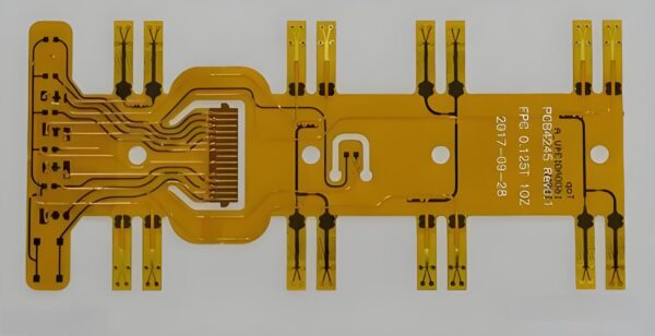
  Multilayer flexible printed circuit boards (FPCs) are at the forefront of modern electronic design, providing both flexibility and durability in high-performance environments. These circuits are made up of multiple layers of flexible material, usually polyimide, which allows them to bend and fold while maintaining their electrical performance. As devices become more compact and complex, especially in automotive, aerospace, and medical applications, the demand for multilayer FPCs continues to rise.


  In this article, we¨ll explore the manufacturing process of multilayer flexible printed circuit boards, highlighting their importance in key industries. We¨ll also emphasize the value of these boards in the European and American markets and how Gekun, a leader in FPC production, offers cutting-edge solutions.


  Multilayer Flexible Printed Circuit Boards


  Multilayer Flexible Printed Circuit Boards


  2. Key Steps in the Manufacturing Process


  Material Selection and Layer Construction


  The manufacturing of multilayer flexible printed circuit boards begins with selecting the appropriate materials. Polyimide is the standard base material due to its high-temperature resistance and flexibility. Copper layers are added to create conductive pathways, and the number of layers depends on the complexity of the design.


  Each layer is carefully constructed, starting with the outer flexible layer, followed by insulating and conductive layers in a sequence. The layers are aligned meticulously to ensure connectivity across all components.


  Imaging and Etching Process


  Once the layers are in place, the next step is to image and etch the copper to define the circuit paths. Photolithography techniques are used to project circuit designs onto the copper layer, which is then etched to remove unwanted areas. This step is critical to creating precise electrical pathways.


  Layer Alignment and Lamination


  After each layer is imaged and etched, the different layers are stacked and aligned using precision machinery. Any misalignment can cause failure in the final product, especially as the complexity of the multilayer flexible printed circuit board increases. The layers are then laminated using heat and pressure to form a single, unified structure.


  Drilling and Plating


  Once laminated, the board is drilled to create vias (small holes) that connect the different layers electrically. These vias are plated with copper to ensure proper conductivity between layers. The drilling and plating processes must be executed with high precision, as any defects can lead to failures in the finished product.


  Testing and Quality Control


  The final steps in the multilayer FPC manufacturing process involve rigorous testing to ensure electrical performance and durability. Automated optical inspection (AOI) systems are often used to detect defects, while electrical testing verifies the connectivity of all circuits. The quality control process ensures that the FPCs meet the high standards required for industries such as automotive, aerospace, and medical devices.


  3. Benefits of Multilayer FPCs in Different Industries


  Consumer Electronics and Automotive Applications


  The flexibility and lightweight nature of multilayer flexible printed circuit boards make them ideal for consumer electronics, such as smartphones and wearable devices. They allow manufacturers to create compact designs while maintaining excellent electrical performance. In the automotive industry, FPCs are used in advanced driver-assistance systems (ADAS) and infotainment systems, providing both durability and flexibility in harsh environments.


  Aerospace and Medical Device Markets


  In aerospace, where weight reduction and reliability are critical, multilayer FPCs offer a solution that meets stringent industry standards. Their ability to function under extreme conditions makes them valuable in aircraft avionics. Similarly, in the medical device sector, FPCs are widely used in diagnostic equipment and implantable devices, where their flexibility and high reliability are essential.


  Multilayer Flexible Printed Circuit Boards


  Multilayer Flexible Printed Circuit Boards


  4. Challenges in Manufacturing Multilayer FPCs


  Complex Design Requirements


  The design of multilayer flexible printed circuit boards presents significant challenges due to the need for precise alignment and electrical performance across multiple layers. Each layer must be carefully planned to ensure that the circuits are properly routed, and the design must accommodate the mechanical stresses that occur during bending and folding.


  Reliability and Durability Concerns


  In applications such as automotive and aerospace, FPCs are exposed to harsh conditions, including extreme temperatures and vibrations. Ensuring that the boards maintain their performance under these conditions requires advanced materials and manufacturing processes, which can increase production costs.


  5. The Role of Gekun in Multilayer FPC Manufacturing


  Gekun is a leader in the multilayer flexible printed circuit board market, providing high-quality solutions tailored to the needs of modern industries. With cutting-edge manufacturing facilities and a focus on innovation, Gekun offers FPCs that meet the most stringent industry standards. Their expertise in multilayer FPC manufacturing ensures that customers receive reliable, high-performance products suited for automotive, aerospace, and consumer electronics markets.


  Gekun¨s commitment to quality and precision makes them a trusted partner for businesses looking to innovate and stay ahead in the competitive market.


  Multilayer Flexible Printed Circuit Boards


  Multilayer Flexible Printed Circuit Boards


  6. Conclusion


  The multilayer flexible printed circuit board manufacturing process is a complex yet crucial aspect of modern electronics. These boards provide the flexibility and durability needed for advanced technologies in automotive, aerospace, and medical industries. By understanding the manufacturing steps, benefits, and challenges associated with multilayer FPCs, businesses can better appreciate their value in the global market.


  Gekun, as a trusted manufacturer, continues to lead the industry with innovative solutions that meet the demands of today¨s fast-paced technology landscape.

Manufacturing Process of Multilayer Flexible Printed Circuit Boards (FPC)

  1. Introduction to Multilayer Flexible Printed Circuit Boards (FPC)In today’s market background, rigid flex pcb Still maintain a strong sales data, and constantly beat the competitors in front of us. https://gekunflex.com/


  Multilayer flexible printed circuit boards (FPCs) are at the forefront of modern electronic design, providing both flexibility and durability in high-performance environments. These circuits are made up of multiple layers of flexible material, usually polyimide, which allows them to bend and fold while maintaining their electrical performance. As devices become more compact and complex, especially in automotive, aerospace, and medical applications, the demand for multilayer FPCs continues to rise.


  In this article, we¨ll explore the manufacturing process of multilayer flexible printed circuit boards, highlighting their importance in key industries. We¨ll also emphasize the value of these boards in the European and American markets and how Gekun, a leader in FPC production, offers cutting-edge solutions.


  Multilayer Flexible Printed Circuit Boards


  Multilayer Flexible Printed Circuit Boards


  2. Key Steps in the Manufacturing Process


  Material Selection and Layer Construction


  The manufacturing of multilayer flexible printed circuit boards begins with selecting the appropriate materials. Polyimide is the standard base material due to its high-temperature resistance and flexibility. Copper layers are added to create conductive pathways, and the number of layers depends on the complexity of the design.


  Each layer is carefully constructed, starting with the outer flexible layer, followed by insulating and conductive layers in a sequence. The layers are aligned meticulously to ensure connectivity across all components.


  Imaging and Etching Process


  Once the layers are in place, the next step is to image and etch the copper to define the circuit paths. Photolithography techniques are used to project circuit designs onto the copper layer, which is then etched to remove unwanted areas. This step is critical to creating precise electrical pathways.


  Layer Alignment and Lamination


  After each layer is imaged and etched, the different layers are stacked and aligned using precision machinery. Any misalignment can cause failure in the final product, especially as the complexity of the multilayer flexible printed circuit board increases. The layers are then laminated using heat and pressure to form a single, unified structure.


  Drilling and Plating


  Once laminated, the board is drilled to create vias (small holes) that connect the different layers electrically. These vias are plated with copper to ensure proper conductivity between layers. The drilling and plating processes must be executed with high precision, as any defects can lead to failures in the finished product.


  Testing and Quality Control


  The final steps in the multilayer FPC manufacturing process involve rigorous testing to ensure electrical performance and durability. Automated optical inspection (AOI) systems are often used to detect defects, while electrical testing verifies the connectivity of all circuits. The quality control process ensures that the FPCs meet the high standards required for industries such as automotive, aerospace, and medical devices.


  3. Benefits of Multilayer FPCs in Different Industries


  Consumer Electronics and Automotive Applications


  The flexibility and lightweight nature of multilayer flexible printed circuit boards make them ideal for consumer electronics, such as smartphones and wearable devices. They allow manufacturers to create compact designs while maintaining excellent electrical performance. In the automotive industry, FPCs are used in advanced driver-assistance systems (ADAS) and infotainment systems, providing both durability and flexibility in harsh environments.


  Aerospace and Medical Device Markets


  In aerospace, where weight reduction and reliability are critical, multilayer FPCs offer a solution that meets stringent industry standards. Their ability to function under extreme conditions makes them valuable in aircraft avionics. Similarly, in the medical device sector, FPCs are widely used in diagnostic equipment and implantable devices, where their flexibility and high reliability are essential.


  Multilayer Flexible Printed Circuit Boards


  Multilayer Flexible Printed Circuit Boards


  4. Challenges in Manufacturing Multilayer FPCs


  Complex Design Requirements


  The design of multilayer flexible printed circuit boards presents significant challenges due to the need for precise alignment and electrical performance across multiple layers. Each layer must be carefully planned to ensure that the circuits are properly routed, and the design must accommodate the mechanical stresses that occur during bending and folding.


  Reliability and Durability Concerns


  In applications such as automotive and aerospace, FPCs are exposed to harsh conditions, including extreme temperatures and vibrations. Ensuring that the boards maintain their performance under these conditions requires advanced materials and manufacturing processes, which can increase production costs.


  5. The Role of Gekun in Multilayer FPC Manufacturing


  Gekun is a leader in the multilayer flexible printed circuit board market, providing high-quality solutions tailored to the needs of modern industries. With cutting-edge manufacturing facilities and a focus on innovation, Gekun offers FPCs that meet the most stringent industry standards. Their expertise in multilayer FPC manufacturing ensures that customers receive reliable, high-performance products suited for automotive, aerospace, and consumer electronics markets.


  Gekun¨s commitment to quality and precision makes them a trusted partner for businesses looking to innovate and stay ahead in the competitive market.


  Multilayer Flexible Printed Circuit Boards


  Multilayer Flexible Printed Circuit Boards


  6. Conclusion


  The multilayer flexible printed circuit board manufacturing process is a complex yet crucial aspect of modern electronics. These boards provide the flexibility and durability needed for advanced technologies in automotive, aerospace, and medical industries. By understanding the manufacturing steps, benefits, and challenges associated with multilayer FPCs, businesses can better appreciate their value in the global market.


  Gekun, as a trusted manufacturer, continues to lead the industry with innovative solutions that meet the demands of today¨s fast-paced technology landscape.

Three countries have been added_ What does it mean for many countries to announce recognition of the Palestinian state_

In addition to these aspects, 卡密回收 The performance in other aspects is also relatively good, which has attracted everyone’s attention and research. https://www.icash.bet

According to a reporter from the head office, on May 22, local time, Norway and Spain respectively announced that they would formally recognize the Palestinian state on May 28. Ireland subsequently announced its formal recognition of the State of Palestine.

From mid-April to early May, Barbados, Jamaica, the Bahamas and other countries have announced the recognition of the State of Palestine. At this stage, nearly 150 countries have recognized the Palestinian State.

What does it mean that more and more countries recognize a Palestinian state?

Three European countries recognized the State of Palestine on the same day

Norwegian Prime Minister Stetler announced on May 22 that Norway will recognize a Palestinian state. Mr Stiller said the approval would take effect on May 28.

Subsequently, Spanish Prime Minister Sanchez announced that the country would recognize a Palestinian state on May 28. In addition, Irish Prime Minister Simon Harris also said that Ireland will formally recognize the Palestinian state.

Israel: recall Ambassador Palestine: welcome the decision of the three countries

After Norway and other three countries announced their recognition of the Palestinian state, Israeli Foreign Minister Katz immediately said that he would recall Israel’s ambassadors to Norway and Ireland. Katz said the move sent a clear message to Norway and Ireland that Israel would not remain silent.

It is reported that Israel has also recalled its ambassador to Spain, but the Israeli Foreign Ministry has not yet publicly confirmed the recall of the ambassador to Spain. Katz will also summon the ambassadors of the three European countries to Israel to condemn the three countries’ decision to recognize a Palestinian state. It is reported that Katz will show ambassadors a video of Israeli female soldiers being detained by Hamas militants.

Palestinian President Abbas issued a statement highly appreciating and welcoming the recognition of the Palestinian state by the three European countries on the same day. The statement said that the decision of the three countries is a salvation of the Palestinian-Israeli two-state solution, which urges all countries in the world to follow the example of Norway, Ireland and Spain to recognize the Palestinian state and support the realization of peace and stability on the basis of the two-state solution.

On the same day, the Palestinian Islamic Resistance Movement (Hamas) also issued a statement welcoming the initiative of the three European countries.

Recently, these countries have recognized the Palestinian state one after another.

On 19 April, Barbados announced its decision to formally recognize Palestine as a State.

On 22 April, the Ministry of Foreign Affairs of Jamaica issued a statement formally recognizing the State of Palestine.

On 2 May, Trinidad and Tobago decided at a cabinet meeting to formally recognize the State of Palestine.

On 7 May, the Ministry of Foreign Affairs of the Bahamas issued a statement that the Bahamas had decided to formally recognize the State of Palestine.

On May 10, the tenth emergency special session of the United Nations General Assembly adopted a resolution by a vote of 143 to 9, with 25 abstentions, determining that the State of Palestine was qualified as a member of the United Nations under the Charter of the United Nations and should be accepted as a member of the United Nations.

What does it mean for more and more countries to recognize a Palestinian state?

Qin Tian, Deputy Director of the Middle East Research Institute of the China Institute of Modern International Relations:

On 10 May, the tenth emergency special session of the United Nations General Assembly adopted a resolution by an overwhelming majority, affirming that the State of Palestine conforms to the membership of the United Nations as stipulated in the Charter of the United Nations and should be accepted as a member of the United Nations. This has put some pressure on some Western countries.

At the same time, Israel has stepped up its offensive against Rafah in southern Gaza, casting a shadow over the prospect of peace between Palestine and Israel. Under this pressure, countries that do not have too deep ties with Israel are the first to take the step of diplomatically recognizing a Palestinian state.

Although this is only the behavior of some countries, the impact is considerable, which exerts certain pressure on Israel, which is diplomatic and moral support beneficial to Palestine. It will also help the two sides to reach a Palestinian-Israeli peace settlement on a more equal basis in the future.